❞ كتاب الاميتر ❝

❞ كتاب الاميتر ❝

فديو مشروح فيه الاميتر.

Expt 19-Ampmeter & Voltmeter and Ohmmeter-English Version, Page 1 of 24
Experiment

Ammeter, Voltmeter, and Ohmmeter
I. Purpose

Understanding the structure of the ammeter, voltmeter, and ohmmeter. Learning how to use
those meters and using them to measure the current, voltage, and resistance of an electric circuit.
II. Pri
nciple

Major referred w
eb site:
http://www.allaboutcircuits.com/vol_1/chpt_8/1.html
A.
What is a meter?
A
meter
is any device built to accurately detect and display an electrical quantity in a form readable
by a human being. Usually this "readable form" is
visual: motion of a pointer on a scale, a series of
lights arranged to form a "bargraph," or some sort of display composed of numerical figures. In the
analysis and testing of circuits, there are meters designed to accurately measure the basic quantities
of voltage, current, and resistance. There are many other types of meters as well, but this
experiment
primarily covers the design and operation of the basic three.
Most modern meters are "digital" in design, meaning that their readable display is in the
form of
numerical digits. Older designs of meters are mechanical in nature, using some kind of pointer
device to show quantity of measurement. In either case, the principles applied in adapting a display
unit to the measurement of (relatively) large quanti
ties of voltage, current, or resistance are the
same.
The display mechanism of a meter is often referred to as a
movement
, borrowing from its
mechanical nature to
move
a pointer along a scale so that a measured value may be read. Though
modern digital met
ers have no moving parts, the term "movement" may be applied to the same
basic device performing the display function.
The design of digital "movements" is beyond the scope of this chapter, but mechanical meter
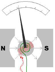
movement designs are very understandable. Mo
st mechanical movements are based on the principle
of electromagnetism: that electric current through a conductor produces a magnetic field
perpendicular to the axis of electron flow. The greater the electric current, the stronger the magnetic
field produc
ed. If the magnetic field formed by the conductor is allowed to interact with another
magnetic field, a physical force will be generated between the two sources of fields. If one of these
sources is free to move with respect to the other, it will do so as
current is conducted through the
wire, the motion (usually against the resistance of a spring) being proportional to strength of
current.
The first meter movements built were known as
galvanometers
, and were usually designed with
maximum sensitivity in mi
nd. A very simple galvanometer may be made from a magnetized needle
(such as the needle from a magnetic compass) suspended from a string, and positioned within a coil
of wire. Current through the wire coil will produce a magnetic field which will deflect t
he needle
from pointing in the direction of earth's magnetic field. An antique string galvanometer is shown in
Expt 19-Ampmeter & Voltmeter and Ohmmeter-English Version, Page 23 of 24
1.
Measure the resistance(~39k
Ω
) by
the
ohmmeter.
2.
Measure the resistance by a multimeter, compare the results of those tow meters.
3.
When using your ohmmeter to measure the resistance 300 k
Ω
or 390 k
Ω
, how accurate the
ohmmeter can be?
IV.

Questions
1.
In Fig. 1, measure the current pass through the 150
Ω
resistance by y
our ammeter. Compare
the voltage different of the ammeter and the resistance.
2.
In Fig. 2(a), measure the voltage different of the 150
Ω
resistance by your voltmeter. And
what is the current pass through your voltmeter?
3.
As shown in Fig 4, combine a galvanometer and three resistances
R
1
,
R
2
, and
R
3
to become a
multi-range ammeter with range 1 A, 0.1 A and 0.01 A. What is the magnitude of those
resistances should be use?
Fig. 4
The configuration of the internal resistors in a multi-range ammeter.
4.
The structure of multi-range voltmeter is shows in Fig. 5. To satisfy the range 2.5V, 10V, and
50V, what is the magnitude of the resistances -
من كتب الإلكترونيات والطاقة - مكتبة كتب تقنية المعلومات.


نبذة عن الكتاب:
الاميتر

فديو مشروح فيه الاميتر.

Expt 19-Ampmeter & Voltmeter and Ohmmeter-English Version, Page 1 of 24
Experiment

Ammeter, Voltmeter, and Ohmmeter
I. Purpose

Understanding the structure of the ammeter, voltmeter, and ohmmeter. Learning how to use
those meters and using them to measure the current, voltage, and resistance of an electric circuit.
II. Pri
nciple

Major referred w
eb site:
http://www.allaboutcircuits.com/vol_1/chpt_8/1.html
A.
What is a meter?
A
meter
is any device built to accurately detect and display an electrical quantity in a form readable
by a human being. Usually this "readable form" is
visual: motion of a pointer on a scale, a series of
lights arranged to form a "bargraph," or some sort of display composed of numerical figures. In the
analysis and testing of circuits, there are meters designed to accurately measure the basic quantities
of voltage, current, and resistance. There are many other types of meters as well, but this
experiment
primarily covers the design and operation of the basic three.
Most modern meters are "digital" in design, meaning that their readable display is in the
form of
numerical digits. Older designs of meters are mechanical in nature, using some kind of pointer
device to show quantity of measurement. In either case, the principles applied in adapting a display
unit to the measurement of (relatively) large quanti
ties of voltage, current, or resistance are the
same.
The display mechanism of a meter is often referred to as a
movement
, borrowing from its
mechanical nature to
move
a pointer along a scale so that a measured value may be read. Though
modern digital met
ers have no moving parts, the term "movement" may be applied to the same
basic device performing the display function.
The design of digital "movements" is beyond the scope of this chapter, but mechanical meter
movement designs are very understandable. Mo
st mechanical movements are based on the principle
of electromagnetism: that electric current through a conductor produces a magnetic field
perpendicular to the axis of electron flow. The greater the electric current, the stronger the magnetic
field produc
ed. If the magnetic field formed by the conductor is allowed to interact with another
magnetic field, a physical force will be generated between the two sources of fields. If one of these
sources is free to move with respect to the other, it will do so as
current is conducted through the
wire, the motion (usually against the resistance of a spring) being proportional to strength of
current.
The first meter movements built were known as
galvanometers
, and were usually designed with
maximum sensitivity in mi
nd. A very simple galvanometer may be made from a magnetized needle
(such as the needle from a magnetic compass) suspended from a string, and positioned within a coil
of wire. Current through the wire coil will produce a magnetic field which will deflect t
he needle
from pointing in the direction of earth's magnetic field. An antique string galvanometer is shown in
Expt 19-Ampmeter & Voltmeter and Ohmmeter-English Version, Page 23 of 24
1.
Measure the resistance(~39k
Ω
) by
the
ohmmeter.
2.
Measure the resistance by a multimeter, compare the results of those tow meters.
3.
When using your ohmmeter to measure the resistance 300 k
Ω
or 390 k
Ω
, how accurate the
ohmmeter can be?
IV.

Questions
1.
In Fig. 1, measure the current pass through the 150
Ω
resistance by y
our ammeter. Compare
the voltage different of the ammeter and the resistance.
2.
In Fig. 2(a), measure the voltage different of the 150
Ω
resistance by your voltmeter. And
what is the current pass through your voltmeter?
3.
As shown in Fig 4, combine a galvanometer and three resistances
R
1
,
R
2
, and
R
3
to become a
multi-range ammeter with range 1 A, 0.1 A and 0.01 A. What is the magnitude of those
resistances should be use?
Fig. 4
The configuration of the internal resistors in a multi-range ammeter.
4.
The structure of multi-range voltmeter is shows in Fig. 5. To satisfy the range 2.5V, 10V, and
50V, what is the magnitude of the resistances
. المزيد..

تعليقات القرّاء:

from pointing in the direction of earth's magnetic field. An antique string galvanometer is shown in 
Expt 19-Ampmeter & Voltmeter and Ohmmeter-English Version, Page 23 of 24 
1.
Measure the resistance(~39k
Ω
) by 
the
 ohmmeter.
2.
Measure the resistance by a multimeter, compare the results of those tow meters. 
3.
When using your ohmmeter to measure the resistance 300 k
Ω
  or 390 k
Ω
, how accurate the 
ohmmeter can be?
IV.

Questions
1.
In  Fig.  1,  measure  the  current  pass  through  the  150
Ω
  resistance  by  y
our  ammeter.  Compare 
the voltage different of the ammeter and the resistance.
2.
In  Fig.  2(a),  measure  the  voltage  different  of  the  150
Ω
  resistance  by  your  voltmeter.  And 
what is the current pass through your voltmeter?
3.
As shown in Fig  4, combine a galvanometer and three resistances 
R
1

R
2
, and 
R
3
 to become a 
multi-range  ammeter  with  range  1  A,  0.1  A  and  0.01  A.  What  is  the  magnitude  of  those 
resistances should be use?   
Fig. 4
 The configuration of the internal resistors in a multi-range ammeter. 
4.
The structure of multi-range voltmeter is shows in Fig. 5. To satisfy the range 2.5V, 10V, and 
50V, what is the magnitude of the resistances 
R
1

R
2
, and 
R
3
 should be? 

الاميتر pdf
معلومات عن جهاز الاميتر
جهاز الاميتر الرقمي
مكونات جهاز الاميتر
تعريف جهاز الفولتميتر
كيف يتم توصيل جهاز الاميتر في الدائرة لقراءة التيار
الاميتر والفولتميتر من حيث الاستخدام
تركيب جهاز الفولتميتر
مكونات جهاز الفولتميتر


حجم الكتاب عند التحميل : 488.1 كيلوبايت .
نوع الكتاب : pdf.
عداد القراءة: عدد قراءة الاميتر

اذا اعجبك الكتاب فضلاً اضغط على أعجبني
و يمكنك تحميله من هنا:

تحميل الاميتر
شكرًا لمساهمتكم

شكراً لمساهمتكم معنا في الإرتقاء بمستوى المكتبة ، يمكنكم االتبليغ عن اخطاء او سوء اختيار للكتب وتصنيفها ومحتواها ، أو كتاب يُمنع نشره ، او محمي بحقوق طبع ونشر ، فضلاً قم بالتبليغ عن الكتاب المُخالف:

برنامج تشغيل ملفات pdfقبل تحميل الكتاب ..
يجب ان يتوفر لديكم برنامج تشغيل وقراءة ملفات pdf
يمكن تحميلة من هنا 'http://get.adobe.com/reader/'